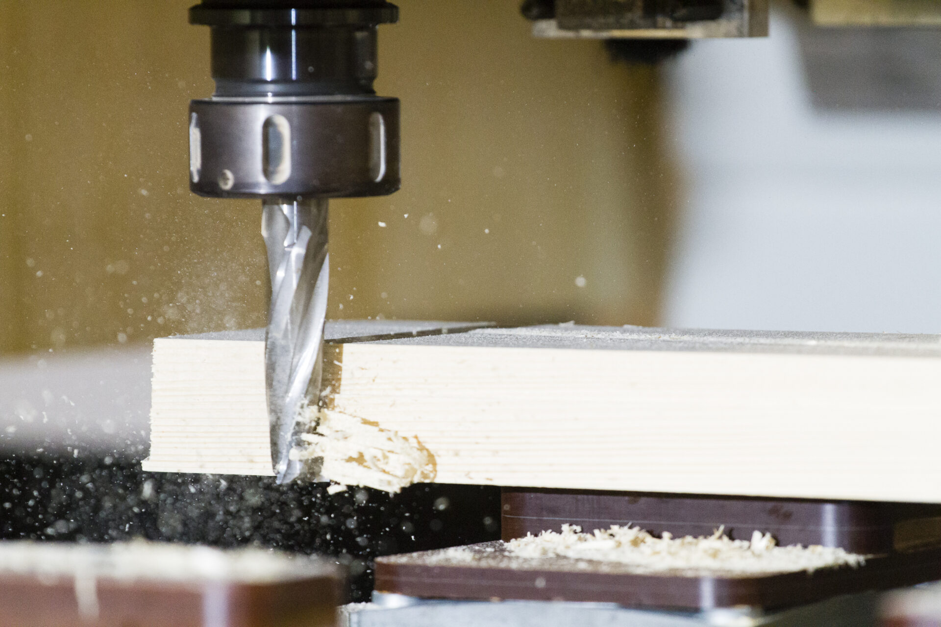
This week starts with Professor Neil's Wednesday lecture, and the next day from our instructors, Mr.Jogin Francis and Mr. Mufeed, we learn about computer-controlled machining, related terminologies, how to use ShopBot, and the safety measures of the machine.
🪧
This week is one of the most challenging for me. I was inspired to build a sleeper-lounge chair to use for myself during my time at Fab Academy. Then I decided to implement the rocking chair concept. The size of the plywood was the primary factor. Each student could only have one piece of plywood. During the design process, I encountered discouragement from one of my instructors, who brought up the case of the student who made a rocking chair. He completed it by utilising the unused plywood of his peers. However, I decided to move on and challenged myself to design and cut my own plywood. I then take measurements of the plywood and design it accordingly, which is not an easy task. I need to consider the centre of gravity, and finally, the main goal is to rock. I customised the design to fit my body perfectly within the plywood's dimensions. Finally, I completed my design that could fit with a single piece of plywood.
Reference Design
🚨
I decided to check out Pinterest for the reference design. Pinterest contains a lot of cool designs using wood. I took two rocking chair photos that are mentioned below as a reference to my design.
Fusion360 Design
⬇️
I followed a few YouTube tutorials, listed below, to gain an overview of designing furniture in Fusion 360.
The image below illustrates the initial sketch of the rocking lounge sleeper chair.
🚨
The first step in designing the CAD model of the rocking sleep chair was to draw on a piece of paper.
🚨
Then I created a CAD model in Fusion 360, and that is illustrated below.
🚨
Then, using Fusion 360, I created a CAD model, as shown below.
🚨
I used the Fusion 360 centre of mass tool to view the centre of the mass in the design, which is illustrated below. I did a few analyses on this design, and I found that it has a few drawbacks. Placing the upper body on the right-hand side of the illustration below could lead to a situation where my upper body is at a lower altitude than my lower body, causing more blood to flow towards the brain, which could be problematic for me.
🚨
So I decided to redesign it.
🚨
Even though this design was not proper, I decided to use Zund to cut a scaled-down version of it in cardboard. I took advantage of this opportunity to test out the "Silicer for Fusion 360" software. This software is not the proper way to test the scaled-down version of the design. Design 2 outlines the correct method for reducing the size of the design and testing it. However, for this design, I went with the Slicer software because I knew I had to change my design and also explore the software.
Slicer for Fusion360
It is a software that turns your 3D models into artefacts . It slices and converts 3D models into 2D patterns that you can laser cut out of any flat material, such as Plywood, Cardboard or Plastic.
⬇️
Follow the link below to download Slicer for Fusion 360.
The image below shows the arrange parts of the lounge chair.
🚨
Then I created a new sketch on the top of one of the parts and then projected the outline of all the parts and saved the sketch.
🚨
Right click the last sketch and save the sketch as DXF file.
Scaled Down Design
🚨
I utilized the scale sketch feature in Fusion 360 to scale down the sketch. The scale value is obtained by doing simple math. The thickness of the slot is 18 mm and the cardboard thickness is 3mm. So I need to convert 18 mm to 3 mm. So the scale value is 1/6.
🚨
Once I scaled down the projected sketch I used Zund to cut it in cardboard. This step is a vital in this week. The scaled-down version of the design gives a clear understanding on how the design looks and act like in real size.
⬇️
Follow the link below to learn how to use the mighty Zund.
I used Zund to cut the scaled-down version of the lounge chair and assembled it, as shown below.
🚨
The image below shows multiple views of the assembled scaled-down design.
Dogbone Fillets
In Fusion 360, a dog bone fillet is a type of fillet used in CAD modeling, particularly in mechanical design. It's commonly used in woodworking or CNC machining when designing parts that have intersecting slots or holes that meet at right angles.
The name "dog bone" comes from its shape resembling a dog bone, with a rounded end and two narrower ends. The purpose of a dog bone fillet is to ensure that a sharp inside corner doesn't interfere with the insertion or movement of a mating part or tool.
🚨
The image below illustrates the tool and its path. Basically, the tool will mill the sharp corners marked as red areas in the figure below. So the parts won’t fit together. We use a dog bone fillet to solve this problem.
🚨
The figure below illustrates the creation and application of the dog bone fillet. If the tool has a diameter of 6 mm, then the dog bone has a diameter of 6.1 mm. The tool will follow the edges, ensuring it remains tangent to them. Applying the dog bone fillet to the sharp corner will make it easier for the machine to form the fillet and continue moving along the edges.
🚨
The image below depicts how it looks after the dog bone fillet is added to the sharp corners. In my case, I selected all the parts, and the tool diameter is 6 mm and the radial offset is 0.1 mm.
Nifty Dogbone in Fusion 360
When cutting out shapes with sharp internal corners, like squares or rectangles, the cutter radius of the tool creates rounded corners. This can cause issues when trying to fit pieces together, especially in joinery where precise fits are necessary. The Nifty Dogbone feature automatically adds these rounded corners to ensure a proper fit during assembly.
⬇️
Follow the link below to install Nifty Dogbone fillet.
After successfully installing the plug-in, select "Nifty DogBone" from the modify tab. Select all the required parts and provide the tool diameter and radial offset values.
🚨
Then click on OK.
🚨
Before dog bone
🚨
After dog bone
Chamfer to Intersecting Edges
🚨
After successfully applying dog bone to the sharp corners, I applied chamfer to all the intersecting edges.
🚨
Now its time to export into DXF file for CNC machining. I created a new sketch on one of the part.
🚨
Then using project feature I selected all the parts and click on OK.
🚨
Finally, I finished the sketch and saved it into a DXF file by right-clicking the sketch and selecting the “Save as DXF” option.
CAD Model
Computer Controlled Cutting
Computer Controlled Cutting refers to the process of using computer-controlled machines, such as laser cutters, CNC (Computer Numerical Control) routers, or plotters, to cut materials into precise shapes or patterns. This technology allows for highly accurate and repeatable cutting operations, making it widely used in various industries, including manufacturing, prototyping, and design.
In Computer Controlled Cutting, the cutting tool is controlled by a computer program that contains specific instructions for the tool path, cutting speed, feed rate, and other parameters. The program is typically created using computer-aided design (CAD) software and then converted into a machine-readable format, such as G-code or STEP-NC.
Common types of Computer Controlled Cutting machines include
Laser Cutters
Use a laser beam to cut through or engrave materials.
CNC Routers
Employ computer numerical control to guide the cutting tool (usually a rotating bit or end mill) across the material.
Plotters:
Cut materials such as paper, vinyl, or fabric based on vector graphics input.
Advantages over traditional manual cutting methods
Precision
Computer control ensures highly accurate and repeatable cuts, with tight tolerances and minimal deviations.
Complexity
Computer-controlled cutting machines can produce complex shapes, intricate details, and precise contours that would be difficult or impossible to achieve with manual cutting techniques.
Automation
Computer-controlled cutting processes can be automated, reducing labor costs and improving consistency and efficiency
Versatility
Computer-controlled cutting machines can be programmed to cut a wide range of materials with varying thicknesses and properties.
ShopBot is a brand of CNC (computer numerical control) routers and machining systems designed for cutting and shaping materials such as wood, plastic, aluminum, and other non-ferrous materials. It is primarily used in woodworking, cabinetry, signage, and other industries that require precision cutting and shaping of materials.
Key features and characteristics of the ShopBot 3-Axis CNC Milling Machine:
Number of Axes
The ShopBot 3-Axis CNC Milling Machine operates in three axes: X, Y, and Z. This means it can move the cutting tool along the horizontal (X and Y) and vertical (Z) directions, allowing for three-dimensional milling and cutting.
Construction
These machines typically have a robust and rigid construction to ensure stability during the machining process. The rigidity of the machine is important for achieving accurate and precise cuts.
Applications
ShopBot CNC milling machines are versatile and can be used for a variety of applications, including woodworking, plastics machining, aluminum milling, and other materials. They are commonly used in industries such as woodworking, signage, and prototyping.
Software Compatibility
ShopBot machines are designed to work with a range of CAD (Computer-Aided Design) and CAM (Computer-Aided Manufacturing) software. Users can create or import digital designs and use the software to generate toolpaths for the CNC machine to follow.
Customization
ShopBot machines often offer options for customization, allowing users to choose the size of the cutting bed, spindle power, and other features based on their specific needs and the type of work they intend to do.
User-Friendly Interface
ShopBot CNC machines typically come with user-friendly interfaces, making it accessible to a broad range of users, including hobbyists, small businesses, and professionals.
Accessories
Various accessories and add-ons, such as dust collection systems, tool changers, and rotary axes, may be available to enhance the capabilities of the machine and accommodate different types of projects.
⬇️
Follow the link below to download the user manual of ShopBot.
Drills and mills are both types of cutting tools used in machining processes, but they serve different purposes and are designed for distinct operations.
Drills:
Purpose
Drills are primarily designed for creating round holes in workpieces. They are specialized cutting tools for hole-making operations.
Operation
Drills operate by rotating and applying axial force to penetrate and remove material from the workpiece.
Geometry
Drill bits typically have a pointed end for initiating the hole and flutes along the length to evacuate chips and coolant. The geometry is optimized for drilling, with a focus on axial forces.
Common Types
Common types of drills include twist drills, center drills, and spotting drills.
Mills:
Purpose
Mills are versatile cutting tools used for a range of operations, including contouring, slotting, facing, and other milling processes. They can perform various cutting tasks beyond hole-making.
Operation
Mills use rotating cutting edges to remove material from the workpiece. The cutting action may be in the axial, radial, or both directions, depending on the type of mill and the operation.
Geometry
Milling tools, also known as end mills, have multiple cutting edges on their cylindrical surface and often feature various cutting geometries. The design allows for side milling, face milling, and slotting operations.
Common Types
Types of mills include end mills, ball mills, roughing end mills, and others, each suited for specific tasks.
Contouring a part means creating a fine finish on an irregular or uneven surface.
In milling, slotting is a process that uses a rotating cutting tool to remove material from a workpiece by moving it in and out of a slot.
In milling, facing is a process that involves cutting a flat surface perpendicular to the milling cutter's axes.
Drill bits vs Mill bits
Drill bits
These rotary cutting tools create cylindrical holes by rotating and applying torque and force. They are used for drilling holes in materials.
Mill bits
Also known as milling cutters or end mills, these tools are used in manual and CNC machines to cut into materials and create holes. They spin around and shave off parts of the material. Mill bits are used in milling machines or machining centers.
These are standard end mills with a flat bottom and sharp corners. They are versatile and suitable for general milling tasks, including slotting and profiling.
Radius End Mills
Similar to square end mills but with a rounded corner, corner radius end mills are useful for reducing stress concentrations in corners and improving the overall durability of the tool.
Ball Nose End Mills
Ball nose end mills have a rounded end, making them ideal for 3D contouring and finishing applications. They are often used for machining curved surfaces.
Formed End Mills
Refer to end mills that have a specific non-standard shape or profile, designed for a specialized machining application. These end mills are crafted to cut specific contours, shapes, or features in a workpiece.
Tapered End Mills
Tapered end mills have a conical shape, which allows for angled or tapered cuts. They are often used in applications where a gradual or angled cut is required.
Chamfer End Mills
Chamfer end mills are designed to create chamfered edges on a workpiece. They are useful for deburring and adding a beveled edge to a part.
V-bits
V-bits are used for fine detail engraving in materials like hardwood, aluminum, brass, and copper. A round bit can't make sharp corners. By using a v-bit and varying the depth, you can make shallow slopes that come to sharp corners and have a mating piece that fits in the negative space
Flutes
Flutes are the sharp, spiral-shaped grooves in a bit that perform cutting work while the bit is spinning. They are the cutting edges on the bit and are responsible for forming and evacuating chips.
A bit with more flutes has more cutting edges and consequently cuts faster and smoother than a bit with fewer flutes
The more flutes a bit has, the thinner these flutes are and the more likely they are to get clogged with material when cutting
2 Flutes
3 Flutes
4 Flutes
•Big chip space • Easy chip ejection • Good for slot milling • Good for heavy duty milling • Less rigidity due to small section area • Lower surface finish
• Chip space almost as big as 2 flutes • Bigger section area - higher rigidity than 2 flutes • Improved surface finish
• Highest rigidity • Biggest section area - small chip space • Gives highest surface finish • Recommended for profiling, side milling and shallow slotting
The helix angle of a drill bit is the angle between the leading edge of the land and the drill axis. It's also known as the rake angle or spiral angle.
The usual range of helix angle used in the drill is 20° to 35°. Large helix angle 45° to 60° suitable for deep holes and softer work materials. The small helix angle of less than 45° is suitable for harder and stronger materials
Upcut vs Downcut vs Compression Bits
In woodworking projects, the right tooling choice is essential for creating ideal results, especially in CNC cutting.
With different flute directions, upcut and downcut bits can achieve different cutting results.
Upcut router bit
The direction of the flutes goes up from left to right. With this design, wood chips are removed up and out of the cut, leaving a clean and smooth bottom surface of the workpiece. Besides, they allow for a faster cut speed because of the efficient removal of chips.
Upcut bits can stay sharper for a longer time since there isn’t a buildup of chips and dust in the cut. However, upcut spiral bits result in a frayed top surface of the workpiece. This type of bit is commonly used in producing mortises and deep grooves or blind holes.
Downcut router bit
Downcut bit features downward flutes from left to right. Downcut spiral bits slowly evacuate wood chips downward, leaving a very crisp and clean top edge without any fraying and splintering.
Unlike an upcut spiral router bit which throws chips out directly, a downcut router bit requires a relatively slower cut speed because it needs more time to remove those chips. If a downcut bit works at a very fast speed, a build-up of wood chips inside the groove may cause overheating or even break the bit.
Downcut bits are suitable for creating shallow grooves or dados on veneers or laminates to prevent tear-out on the top surface. It is also ideal for sizing, trimming, and pattern cutting. However, the bottom edge can be frayed as the chips are going downward and continuously recut.
Feature
Downcut Bits
Upcut Bits
Cutting Action
Flutes spiral in a downward direction.
Flutes spiral in an upward direction.
Chip Evacuation
Pushes chips downward into the cut groove.
Lifts chips upward and away from the cut.
Top Surface Finish
Produces a cleaner top surface by minimizing tear-out.
May cause tearing or fraying on the top surface, especially in materials like wood.
Bottom Surface Finish
Can exert more downward force, potentially causing compression and a rougher bottom surface.
Generally leaves a clean bottom surface.
Material Applications
Ideal for materials where a clean top surface is crucial, like laminates and veneers.
Suitable for materials where efficient chip removal is important, such as wood and plastics.
Common Uses
Finish milling, edge trimming, and cutting laminates or veneered materials.
Roughing and pocketing operations in wood, MDF, and plastics.
Machining Strategy
Preferred for finish passes and achieving clean top surfaces.
Efficient for material removal in bulk.
Considerations
Risk of rough bottom surface and compression.
Potential for fraying on the top surface.
Hybrid Strategies
May be used in conjunction with upcut bits to achieve desired results.
Often used in combination with other bits for multi-pass machining.
Compression Bit
It combines upcut and downcut, thus called “compression”. With a compression bit, it’s easy to create a smooth and clean edge on both sides of the workpiece. The upcut section pulls out the chips quickly and the downcut section smooths the top and bottom edges. However, a compression bit is more expensive and requires professional techniques.
Chip Load
Chip load refers to the quantity of material removed in each chip during machining. It is approximately calculated by dividing the feed rate (in inches per minute) by the product of the RPM (revolutions per minute) and the number of flutes.
📜
Chip Load Equation
ChipLoad(CL)=FeedRate/(RPM×NumberofFlutes)
Chip Load (CL): The amount of material removed in each chip.
Feed Rate: The speed at which the cutting tool moves through the workpiece, measured in inches per minute.
RPM: Revolutions per minute, representing the speed of the cutting tool.
Number of Flutes: The total number of cutting edges on the tool.
In computer-controlled cutting, stepover is the distance a tool moves horizontally between passes. It's usually between 25–40% of the tool's total diameter.
Do's while working on ShopBot
Always ensure that you wear proper ear protection and a good pair of safety glasses when operating a ShopBot.
Ensure that your safety glasses are firmly in place every time you are closely observing the cutting tools.
Ensure that you wear suitable footwear such as safety boots at all times.
If you have long hair, ensure that you keep it covered when you operate the machine.
Keep your hands away from any moving parts during machining processes.
Stand clear of the machine whenever it is operational. You should also warn any other people near the risk of being too close to it.
Whenever you are handling or passing tools, avoid touching the cutting edges.
Ensure that you turn the machine off completely and clean it whenever you have finished using it.
You should wear gloves when you are handling with working with the workpiece but, must not wear it when you are using the computer as you may hit different buttons or wont feel the spindle tightness or whether tool is clamped.
Dont's while working on ShopBot
You should never wear jewelry or any loose clothing.
You should never try to reach into the machine while it’s running.
You should never put your hands anywhere on the work bed when the machine is on and spindle is rotating.
Never leave the machine when it’s not completely powered down.
Safety while wood working
Always use gloves as the chips might get inside you hands
Always use mask, mainly while sanding as the file dust while sanding may have bad impact on you health
Use Goggles as the chips my fly into your airs while operating
Use tight clothes and manage hair
You can use aprons for preventing chips getting into your clothes.
Always use shoes.
Plywood
🚨
The size of the plywood allocated for us was 2440 mm in length and 1220 mm in width, and I considered 18mm as the thickness.
Plywood vs Medium Density Fibreboard (MDF)
⬇️
Follow the link below to learn the difference between plywood and MDF.
Highly recommended to take every precautions and safety measures.
🚨
To protect my eyes and hand I wear safety glass and safety hand glove.
🚨
To protect my ears I used earplugs and ear muffs.
CAM
🚨
It's time to begin the milling process.
🚨
Always measure your stock before cutting and modify the design accordingly, as an improper fit could result in a loose fit or excessive sanding.
🚨
Initially, I placed the plywood on top of the sacrificial layer and decided to move on to the CAM for the machining.
V Carve
V Carve is a software application used for creating and preparing designs specifically for CNC (Computer Numerical Control) routing machines. It allows users to design intricate 2D and 3D models, generate toolpaths, and simulate the machining process. V Carve software is commonly utilized in woodworking, signage, and other industries that involve CNC routing and engraving.
🚨
After obtaining the DXF file from Fusion, I stored it on a USB flash drive and moved it to the PC that connected to the Shopbot.
🚨
I opened the V-Carve Pro software and imported the DXF file by selecting the import vectors option within the File menu. The plywood measures 2440 x 1220 mm and has a thickness of 17.5 mm, despite its advertised 18mm thickness.
🚨
Then I assign plywood attributes such as length, width, and thickness that I plan to use.
🚨
Using the "move," "rotate," and "flip" tools, I made adjustments to the file to ensure that each part would use the maximum amount of material possible.
🚨
I selected all parts, then clicked on the join vectors inside the edit objects, maintaining a tolerance of 0.5 mm, and pressed OK. If it is closer than 0.5mm, this will join the broken curves.
🚨
It's time to create the tool path in V Carve Pro.
🚨
Select the tool.
🚨
To add tabs, press the "add tabs" button on the tool path, specify the tab length and thickness, and then click "edit tabs".
🚨
Then, you can either do it automatically by entering the required tabs per cutout or manually adding them.
🚨
Tabs are the connections between the material to be cut out and the main workpiece so as to maintain the position and prevent moving around, hitting the tool, or ejecting out after the cut is done. Place the tabs in flat areas where sanding is easy. Normally, in the automatic addition of tabs, the software might add it in corners as well, so I prefer adding it manually in flat areas.
🚨
When creating tool paths, it is important to choose whether you want to cut inside or outside of the part. Always ensure that you give commands accordingly.
🚨
Animate the toolpath by clicking the preview toolpath in the toolpath menu to view the simulation and how it cuts.
🚨
Close the preview toolpath and hit save toolpath in the toolpath menu. Check on output all visible toolpaths to one file. Ensure to save the file in the Shopbot TC (MM) (*.sbp) format.
Machining
🚨
Before cutting, it's important to clamp the plywood sheets to the ShopBot platform using screws so that they don't move around.
🚨
The image below illustrates the 6mm endmill used for the machining.
🚨
The image below depicts the variable-frequency drive of the ShopBot.
Zeroing the machine
🚨
To load our file into the ShopBot, we must first zero the machine to the origin point of our material or stock. Click on the remote icon and follow the necessary steps to achieve this.
🚨
After clicking on the remote icon, use the arrows on the remote to jog the ShopBot to the origin point of our material. First, jog the machine along the X and Y axes to the desired origin position. Once the tool is in position, we can click on the "Zero Axes" button and then select the axes we want to zero by clicking on the "ZERO" button. This will zero our machine, and we will be ready to begin the cutting process.
🚨
check the x and y axis.
🚨
Now the x and y axes are set to zero.
🚨
Setting the z axis reference to zero
🚨
This probe is used to zero the machine at z axis, the machine detects the position when the tool and this metal plate comes in contact, this probing plate is an additional accessory of this machine.
🚨
check the z axis.
🚨
Now hit ender
🚨
This message will be shown when it is zeroed.
⚠️
After setting the origin, I strongly advise making a tiny indentation with the milling bit at the beginning, as this allows us to restart by following the mark in the event of a power loss.
🚨
As the CAM is completed, we can open ShopBot’s software to load the CAM toolpath and run the files.
🚨
We can load our file by clicking on “Cut Part”.
🚨
Once the file is uploaded we can START.
🚨
After clicking the "START" button, a window will appear requesting that we switch on the spindle. Use the key on the ShopBot's side panel to turn on the spindle.
⚠️
Turn the key counter clock wise all the way to the end and then turn along clock wise once.
🚨
Also, press the Start button on the physical remote.
🚨
Once the spindle is spinning, we can click "OK," and the Shop Bot will begin running the code line by line. The progress of the code can be viewed on the "Command Console".
⚠️
As soon as the cutting process starts, turn on the dust collector.
⚠️
YOU MUST ALWAYS BE NEAR TO THE SHOPBOT WHEN IT IS OPERATING
Post Processing
🚨
Once the cut is complete, I easily remove these small tabs with the help of a chisel, and then use the jigsaw tool.
🚨
Remove the rest of the material from the bed and clean it for future use.
🚨
Sand the edges and tabs.
🚨
Initially, I used the chisel to remove tabs from the parts, then utilised the grip sander and chamfer tool to post-process the edges and corners. Finally, I used the orbit sander to sand the flat parts.
🚨
The timelapse of the post-processing is provided below.
Final Result 😀
😀
I am really satisfied with the final result, and I felt over the moon.
Challenges
Inadequate plywood
⚠️
This week is one of the most challenging for me. I was inspired to build a sleeper-lounge chair to use for myself during my time at Fab Academy. Then I decided to implement the rocking chair concept. The size of the plywood was the primary factor. Each student could only have one piece of plywood. During the design process, I encountered discouragement from one of my instructors, who brought up the case of the student who made a rocking chair. He completed it by utilising the unused plywood of his peers. However, I decided to move on and challenged myself to design and cut my own plywood. I then take measurements of the plywood and design it accordingly, which is not an easy task. I need to consider the centre of gravity, and finally, the main goal is to rock. I customised the design to fit my body perfectly within the plywood's dimensions. Finally, I completed my design that could fit with a single piece of plywood.
Thickness of the plywood
⚠️
I measured the thickness of the plywood from different sections of the plywood, and instead of taking the average, I chose the highest value. However, I manage to fit the parts, but it is recommended to take the average value of at least 8 values taken from 8 different sections of the plywood using a digital vernier.
There is not enough clearance between the parts
⚠️
While arranging the parts in the Fusion 360 plugin, I gave a clearance of 20 mm between the parts, which is not sufficient for my case. After cutting the first part of my design, I realized this. Despite the tabs, the part started to vibrate, so I cut all of the parts to a depth of around 10 mm. To ensure their safety, I screwed them all to the sacrificial layer.
Tabs were not properly placed
⚠️
During the CAM, I used the auto-tab generation feature, and I found that the tabs were not properly placed. I removed all the tabs and placed the tabs manually.
It took 3 days to complete the machining
⚠️
Finally, this week became one of the most challenging for me because my design consists of 36 parts, and it took more than 35 hours to complete the machining. The workspace is highly noisy and air-polluted, and I had to wear all the safety equipment and a mask and be near the machine during the machining. It took me 3 days to complete the machining.


 https://www.youtube.com/watch?v=VZU_Jpyyc5M


 https://apps.autodesk.com/FUSION/en/Detail/Index?id=3534533763590670806&appLang=en&os=Win64


 https://www.youtube.com/watch?v=FNYEXjRmDtI


 https://www.harveyperformance.com/in-the-loupe/drill-mills-drill-vs-mill/